The block flow diagram is also called a schematic diagram and it is a non-scaled single line diagram. It is also useful for conveying the major piece of equipment.It is very useful to convey the heat and material balances.The process flow diagram conveys the major processing steps represented by the equipment A PFD diagram would contain the process piping, major equipment symbol names and identification numbers, control valves and valves that affect the operation of the system, interconnection with other systems, major bypass and recirculation lines, the composition of fluids, and system ratings operation values like maximum flow temperature and pressure. This type of piping diagram won’t display minor components, piping systems, piping ratings, and designations. This diagram shows the relationship between the components in a system, this type of diagram tabulates the process design values for different operating mode components. Red – Fire protection material WHAT ARE THE TYPES OF PIPING DIAGRAM In a piping arrangement all the equipment, instrument connections with the tag numbers will be shown in a piping arrangement, important details will be on large scale. The primary and the secondary beams are shown as utility stations so that the most proper route for the utility can be determined. The process equipment and piping have priority over the piping arrangement. The vertical lengths of the pipe can be calculated by using elevations, while the horizontal lengths are calculated by using north-south and east-west coordinates.

The pipe lengths are determined by calculations using coordinates and elevations.

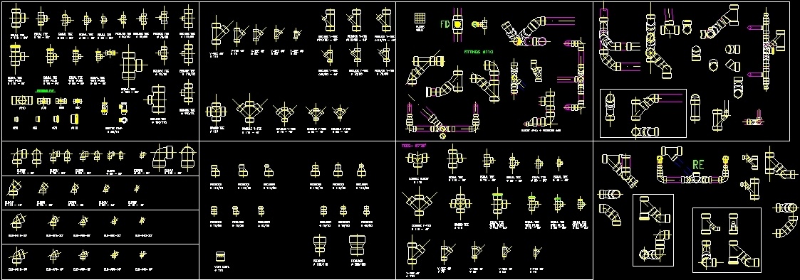
By the help of these drawings and also with the project installation specifications would provide good guidelines to complete the piping system. There are different types of piping diagrams and they are process flow diagrams, piping and instrumentation diagram, orthographic pipe drawing, piping isometrics, and block flow diagrams.

Piping diagrams are designed in a way that will be understandable for non-technical personnel. The drawings would help to speed up the fabrication and erection work at the site. These drawings are schematic representations and they would define functional relationships in a piping system.

The main purpose of a piping drawing is to communicate the information in a simple way.


 0 kommentar(er)
